4 bit shift register design in VHDL testbench and output waveform

A 4-bit shift register design in VHDL is illustrated with waveform output. The shift register is made of 4 D Flip Flop. Data enters 1 bit at a time into the first D Flip Flop which is then shifted along the cascaded shift register.

D Flip Flop:

The D Flop Flip is the basic unit of the 4 bit shift register. It is a synchronous flip flop with clock and reset input. The input for data is D and the output is Q.
d flip flop

D Flip Flop:

library ieee;
use ieee.std_logic_1164.all;

entity dff is
port(
D : in std_logic;
CLK : in std_logic;
RST : in std_logic;
Q : out std_logic
);
end dff;

architecture dff_arch of dff is
begin

process (CLK)
begin
if CLKevent and CLK=1 then  --CLK rising edge
if RST =1 then --synchronous RESET active High
Q <= 0;
else
Q <= D;
end if;
end if;
end process;
end dff_arch;

Shift Register:

The shift register below instantiates the above D Flip Flip 4 times for the 4 Flip Flops. The input to the register is Din which is feed to the first D Flip Flop. The out of the shift register is Qout.

shift register
Shift Register Code:

library ieee;
use ieee.std_logic_1164.all;

entity register_design is
port (
Din : in std_logic;
CLK : in std_logic;
RST : in std_logic;
Qout : out std_logic_vector(3 downto 0)
);
end register_design;

architecture register_arch of register_design is

signal q0, q1, q2, q3 : std_logic;

begin
ff1: entity work.dff(dff_arch)
port map (
D => Din,
CLK => CLK,
RST => RST,
Q => q0
);
ff2: entity work.dff(dff_arch)
port map (
D => q0,
CLK => CLK,
RST => RST,
Q => q1
);
ff3: entity work.dff(dff_arch)
port map (
D => q1,
CLK => CLK,
RST => RST,
Q => q2
);
ff4: entity work.dff(dff_arch)
port map (
D => q2,
CLK => CLK,
RST => RST,
Q => q3
);

Qout <= q0&q1&q2&q3;

end register_arch;

Testbench Code:

library ieee;
use ieee.std_logic_1164.all;

entity register_design_tb is
end register_design_tb;

architecture TB_ARCHITECTURE of register_design_tb is

component register_design
port(
Din : in STD_LOGIC;
CLK : in STD_LOGIC;
RST : in STD_LOGIC;
Qout : out STD_LOGIC_VECTOR(3 downto 0) );
end component;

signal Din : STD_LOGIC;
signal CLK : STD_LOGIC;
signal RST : STD_LOGIC;

signal Qout : STD_LOGIC_VECTOR(3 downto 0);

begin

UUT : register_design
port map (
Din => Din,
CLK => CLK,
RST => RST,
Qout => Qout
);

CLK_GEN: process
begin
CLK <= 0;
wait for 5 ns;

CLK <= 1;
wait for 5 ns;

end process;

stimuli : process
begin

Din <= 1 after 20 ns;

RST <= 1 after 70 ns;

Din <= 1 after 90 ns;

wait;

end process;

end TB_ARCHITECTURE;

configuration TESTBENCH_FOR_register_design of register_design_tb is
for TB_ARCHITECTURE
for UUT : register_design
use entity work.register_design(register_arch);
end for;
end for;
end TESTBENCH_FOR_register_design;

Waveform
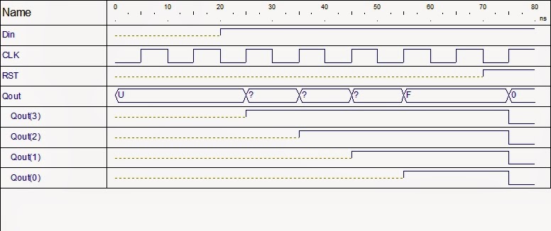
graph waveform of shift register


In the waveform graph above, the data input is 1 at 20 ns which is propagated through the D flip flops as shown by Qout(3), Qout(2), Qout(1) and Qout(0). At 70 ns Reset signal RST is applied which puts all the D flip flop states to 0.
Read More..

Different method of adding component instances to an entity in VHDL

In the FPGA tutorial on how to add component instance in existing entity one method of adding was explained which is without library reference. In this post, other two method of adding instances to an entity are illustrated. The two methods are via VHDL library reference and using configuration declaration block.

The entity was a odd parity generator whose schematic is shown below.
parity generator schematic
The various ways of adding the xor gate was briefly talked in that post.

2. Without component declaration

In this method, library feature is used to add the xor gate. By this what it means is that, the xor gate component are referred using library reference. And in this case there is no need to define the component within the architecture body.

the main code line that references the library is,

instance_unit_name : entity work.component_name(current_entity_architecture_name)

The instance_unit_name is the name of the instance which is newly created. The entity term is required, the work is the library(directory) where the component(eg xor_gate) resides and the current_entity_architecture_name is name of the current entity architecture name.

Lets see the code of that used component declaration is,

library IEEE;
use IEEE.STD_LOGIC_1164.ALL;

entity parity is
    Port ( x1 : in  STD_LOGIC;
           x2 : in  STD_LOGIC;
           x3 : in  STD_LOGIC;
           x4 : in  STD_LOGIC;
           y : out  STD_LOGIC);
end parity;

architecture parity_arch of parity is

component xor_gate
Port ( a1 : in  STD_LOGIC;
             a2 : in  STD_LOGIC;
             b : out  STD_LOGIC);
end component;

signal int1, int2: std_logic;

begin

xor_unit1 : xor_gate
port map(a1 => x1, a2 => x2, b => int1);
xor_unit2 : xor_gate
port map(a1 => x3, a2 => x4, b => int2);

y <= int1 xor int2;

end parity_arch;


The code in red is the component declaration. When using library reference to add component instances, the component declaration in red is not required. At the same time, the component instantiation lines in yellow needs to be changed such that it references to library where the component gate vhdl code resides.

Making the necessary changes, the code for the parity generator becomes-

library IEEE;
use IEEE.STD_LOGIC_1164.ALL;

entity parity is
    Port ( x1 : in  STD_LOGIC;
           x2 : in  STD_LOGIC;
           x3 : in  STD_LOGIC;
           x4 : in  STD_LOGIC;
           y : out  STD_LOGIC);
end parity;

architecture parity_arch of parity is

signal int1, int2: std_logic;

begin

xor_unit1 : entity work.xor_gate(parity_arch)
port map(a1 => x1, a2 => x2, b => int1);
xor_unit2 : entity work.xor_gate(parity_arch)
port map(a1 => x3, a2 => x4, b => int2);

y <= int1 xor int2;

end parity_arch;


3. Using Configuration declaration:

Another method of adding component instance in the entity in VHDL is using configuration declaration. This differs from the above two methods in that, the port mapping is done in the architecture section while the VHDL library reference is done in a separate configuration section. Also the component declaration is added back.

The following code illustrates this.

library IEEE;
use IEEE.STD_LOGIC_1164.ALL;

entity parity is
    Port ( x1 : in  STD_LOGIC;
           x2 : in  STD_LOGIC;
           x3 : in  STD_LOGIC;
           x4 : in  STD_LOGIC;
           y : out  STD_LOGIC);
end parity;

architecture parity_arch of parity is

component xor_gate
Port ( a1 : in  STD_LOGIC;
             a2 : in  STD_LOGIC;
             b : out  STD_LOGIC);
end component;

signal int1, int2: std_logic;

begin

xor_unit1: xor_gate port map(x1, x2, int1);
xor_unit2: xor_gate port map(x3, x4, int2);

y <= int1 xor int2;

end parity_arch;

configuration parity_config of parity is

for parity_arch 
for xor_unit1 : xor_gate
use entity work.xor_gate(xor_arch);
end for;
for xor_unit2 : xor_gate
use entity work.xor_gate(xor_arch);
end for;
end for;

end parity_config;


Thus there are different method of adding the component instance to a entity.

See other FPGA tutorials also.
Read More..

how to create and use functions in VHDL

This is a continuation of the tutorial- how to create and use functions in VHDL. In this tutorial we show how a function can be declared inside an entity section. In the last two tutorials we showed how a function can be declared in a package and how a function can be declared inside the architecture.

The code below is the function we created that accepts two inputs of the type std_logic_vector and outputs one parameter also of the type std_logic_vector.

FUNCTION myAdder(signal f1,f2: STD_LOGIC_vector(3 downto 0)) return std_logic_vector IS
    variable sum_int : integer := 0;
    variable sum : std_logic_vector(3 downto 0) := "0000";
BEGIN
 
    sum_int := to_integer(unsigned(f1)) + to_integer(unsigned(f2));
 
    sum := std_logic_vector(to_unsigned(sum_int,4));
 
    return sum;
 
END FUNCTION myAdder;

As you might already guessed from the two earlier tutorials, once you have create the function VHDL code, the placement of the function is just matter of copying and pasting the code inside a package or architecture declarative part. The placement of function code in entity is similar of that of architecture method. The function code is just placed after the port declaration and the function is called in the architecture after the begin keyword.

 The following shows where to place the function code in the function declaration in entity method:

 library ieee;
use ieee.std_logic_1164.all;
use ieee.numeric_std.all;

entity function_test is
    port(
    a : in std_logic_vector(3 downto 0);
    b : in std_logic_vector(3 downto 0);
    y : out std_logic_vector(3 downto 0)
    );
 
FUNCTION myAdder(signal f1,f2: STD_LOGIC_vector(3 downto 0)) return std_logic_vector IS
    variable sum_int : integer := 0;
    variable sum : std_logic_vector(3 downto 0) := "0000";
BEGIN
 
    sum_int := to_integer(unsigned(f1)) + to_integer(unsigned(f2));
 
    sum := std_logic_vector(to_unsigned(sum_int,4));
 
    return sum;
 
END FUNCTION myAdder;

end function_test;

architecture model of function_test is

begin
 
    y <= myAdder(a, b);

end model;

 There is difference in the package method though. In the package method, we declared the function header inside the package header and the whole function(header and body) inside the package body.

In case of entity and architecture method, the whole function code(header and body) is declared inside the entity or architecture whichever method is used. 

Read More..

How to design Ripple Carry Adder using For Loop in VHDL

This VHDL tutorial shows how to design Ripple Carry Adder using For Loop in VHDL. A ripple carry adder is one in which the carry output from each full adder circuit is propagated to the next full adder to contribute to the calculation. A Loop statement is one of the four sequential statement in VHDL. The others are the IF statement, Case statement and the Wait statement.

The Loop statement is used with other VHDL keywords such as For, While, Next and Exit. So there are different forms of Loop statement depending upon which(For, While, Next and Exit) keyword is used. Here we illustrate the Loop statement with For keyword for the design of Ripple Carry Adder.

One Full adder has 3 inputs, the two input bits for the number to be added, one carry input from previous calculation and two outputs- the sum and carry out. Schematic symbol of a Full Adder is shown below:


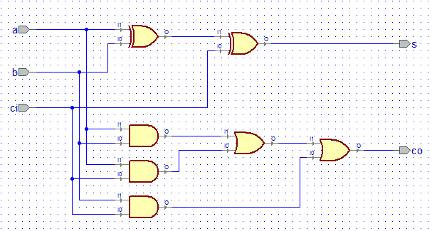
Internally the Full Adder is constructed using basic logic gates implementing the Boolean function of a full adder circuit as follows-

full adder circuit

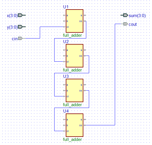
Now the carry ripple term refers to the fact that the previous carry input is the input to the carry input of the first adder. The first adder carry output is connected to the next full adder carry input, whose carry output is again connected to the next full adder carry input and so on as illustrated by the diagram below:

carry propagation in ripple carry adder

When one looks at the Boolean equation for the N bit adder implementation for each of the full adder we see that there is some repetivitive structure in the code:

first adder:
        sum(0) = x(0) xor y(0) xor c(0);
        c(1) := (x(0) and y(0)) or (x(0) and c(0)) or (y(0) and c(0));
 where c(1) is from the first adder

second adder:
        sum(1) = x(1) xor y(1) xor c(1);
        c(2) := (x(1) and y(1)) or (x(1) and c(1)) or (y(1) and c(1));

 third adder:
        sum(2) = x(2) xor y(2) xor c(2);
        c(3) := (x(2) and y(2)) or (x(2) and c(2)) or (y(2) and c(2)); 

fourth adder:
        sum(3) = x(3) xor y(3) xor c(3);
        c(4) := (x(3) and y(3)) or (x(3) and c(3)) or (y(3) and c(3));

So if we take c(0) to be cin of the carry input of the 4 bit adder and c(4) the cout of the 4 bit adder then the 4 bit adder can be designed.

Because of the repetivitive structure in the code we can use for loop to implement the structure,

for k in 0 to 3 loop
      sum(k) = x(k) xor y(k) xor c(k);
        c(k+1) := (x(k) and y(k)) or (x(k) and c(k)) or (y(k) and c(k));
end loop;

To use the above VHDL loop code we need the c to be of variable type and having a bit vector length of 5 bits- 4 downto 0 if signal x and y and sum are 3 downto 0.

The complete ripple carry adder VHDL code is below:


library ieee;
use ieee.std_logic_1164.all;

entity ripple_carry_adder is
    port(
    x : in std_logic_vector(3 downto 0);
    y : in std_logic_vector(3 downto 0);
    cin : in std_logic;
    sum : out std_logic_vector(3 downto 0);
    cout : out std_logic
    );
end ripple_carry_adder;

architecture model of ripple_carry_adder is

begin
    process(x,y,cin)
        variable c : std_logic_vector(4 downto 0);
    begin       
        c(0) := cin;
    for k in 0 to 3 loop
        sum(k) <= x(k) xor y(k) xor c(k);
        c(k+1) := (x(k) and y(k)) or (x(k) and c(k)) or (y(k) and c(k));
    end loop;
   
    cout <= c(4);
   
    end process;
       
end model;

The schematic model is shown below:
 
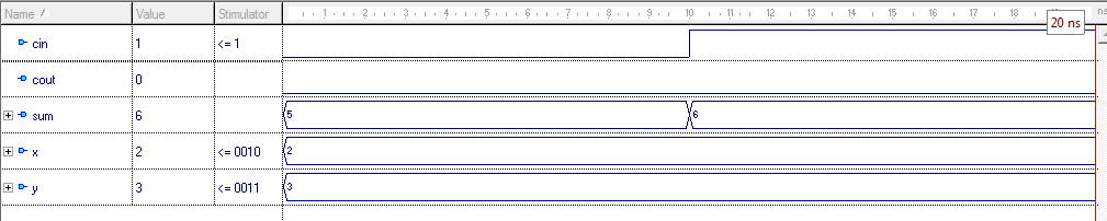
 The following shows the simulated waveform for this adder using VHDL software:

ripple carrry adder simulation vhdl software

So, this vhdl tutorial showed you how and why a for loop vhdl statement can be used for modelling ripple carry adder.
Read More..

How to realize encoder function in VHDL

There are many ways in which encoder function can be implemented in VHDL. Here 4 different techniques with VHDL codes are provided.

Suppose we to design an encoder which outputs y with sel input as follows,

when sel is 00, y is 1110
when sel is 01, y is 1101
when sel is 10, y is 1011
when sel is 11, y is 0111

So the input sel is 2 bit and output y is 4 bit. The the encoder entity can be declared as follows-

entity encoder is
    port(
    sel : in std_logic_vector(1 downto 0);
    y : out std_logic_vector(3 downto 0)
    );
end encoder;

Now there are different ways to realize the encoder function.

1. Using if then elsif statements inside a process

architecture arch1 of encoder is
begin
    process(sel)
    begin
        y <= (yrange => 1);
        if (sel = "00") then y(0) <= 0;
        elsif (sel = "01") then y(1) <= 0;
        elsif (sel = "10") then y(2) <= 0;
        else y(3) <= 0;
        end if;
    end process;
end arch1;

2. Using case statement inside a process

architecture arch2 of encoder is
begin
    process(sel)
    begin
        y <= (yrange => 1);
        case sel is
            when "00" => y(0) <= 0;
            when "01" => y(1) <= 0;
            when "10" => y(2) <= 0;
            when others => y(3) <= 0;
        end case;
    end process;
   
end arch2;

3. Using simple select statement

architecture arch3 of encoder is
begin
    with sel select
    y <= "1110" when "00",
    "1101" when "01",
    "1011" when "10",
    "0111" when others;
end arch3;

4. Using conversion of sel inputs bits to integer and setting it to 0

architecture arch4 of encoder is
begin
    process(sel)
    begin
        y <= (yrange => 1);
        y(to_integer(unsigned(sel))) <= 0;
    end process;
end arch4;
Read More..

Blog Archive

Powered by Blogger.