This VHDL tutorial shows how to design Ripple Carry Adder using For Loop in VHDL. A ripple carry adder is one in which the carry output from each full adder circuit is propagated to the next full adder to contribute to the calculation. A Loop statement is one of the four sequential statement in VHDL. The others are the IF statement, Case statement and the Wait statement.
The Loop statement is used with other VHDL keywords such as For, While, Next and Exit. So there are different forms of Loop statement depending upon which(For, While, Next and Exit) keyword is used. Here we illustrate the Loop statement with For keyword for the design of Ripple Carry Adder.
One Full adder has 3 inputs, the two input bits for the number to be added, one carry input from previous calculation and two outputs- the sum and carry out. Schematic symbol of a Full Adder is shown below:

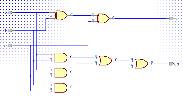
Internally the Full Adder is constructed using basic logic gates implementing the Boolean function of a full adder circuit as follows-

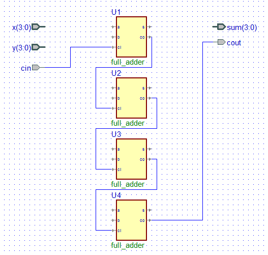
Now the carry ripple term refers to the fact that the previous carry input is the input to the carry input of the first adder. The first adder carry output is connected to the next full adder carry input, whose carry output is again connected to the next full adder carry input and so on as illustrated by the diagram below:

When one looks at the Boolean equation for the N bit adder implementation for each of the full adder we see that there is some repetivitive structure in the code:
first adder:
sum(0) = x(0) xor y(0) xor c(0);
c(1) := (x(0) and y(0)) or (x(0) and c(0)) or (y(0) and c(0));
where c(1) is from the first adder
second adder:
sum(1) = x(1) xor y(1) xor c(1);
c(2) := (x(1) and y(1)) or (x(1) and c(1)) or (y(1) and c(1));
third adder:
sum(2) = x(2) xor y(2) xor c(2);
c(3) := (x(2) and y(2)) or (x(2) and c(2)) or (y(2) and c(2));
fourth adder:
sum(3) = x(3) xor y(3) xor c(3);
c(4) := (x(3) and y(3)) or (x(3) and c(3)) or (y(3) and c(3));
So if we take c(0) to be cin of the carry input of the 4 bit adder and c(4) the cout of the 4 bit adder then the 4 bit adder can be designed.
Because of the repetivitive structure in the code we can use for loop to implement the structure,
for k in 0 to 3 loop
sum(k) = x(k) xor y(k) xor c(k);
c(k+1) := (x(k) and y(k)) or (x(k) and c(k)) or (y(k) and c(k));
end loop;
To use the above VHDL loop code we need the c to be of variable type and having a bit vector length of 5 bits- 4 downto 0 if signal x and y and sum are 3 downto 0.
The complete ripple carry adder VHDL code is below:
library ieee;
use ieee.std_logic_1164.all;
entity ripple_carry_adder is
port(
x : in std_logic_vector(3 downto 0);
y : in std_logic_vector(3 downto 0);
cin : in std_logic;
sum : out std_logic_vector(3 downto 0);
cout : out std_logic
);
end ripple_carry_adder;
architecture model of ripple_carry_adder is
begin
process(x,y,cin)
variable c : std_logic_vector(4 downto 0);
begin
c(0) := cin;
for k in 0 to 3 loop
sum(k) <= x(k) xor y(k) xor c(k);
c(k+1) := (x(k) and y(k)) or (x(k) and c(k)) or (y(k) and c(k));
end loop;
cout <= c(4);
end process;
end model;
The schematic model is shown below:
 The following shows the simulated waveform for this adder using VHDL software:

So, this vhdl tutorial showed you how and why a for loop vhdl statement can be used for modelling ripple carry adder.
The Loop statement is used with other VHDL keywords such as For, While, Next and Exit. So there are different forms of Loop statement depending upon which(For, While, Next and Exit) keyword is used. Here we illustrate the Loop statement with For keyword for the design of Ripple Carry Adder.
One Full adder has 3 inputs, the two input bits for the number to be added, one carry input from previous calculation and two outputs- the sum and carry out. Schematic symbol of a Full Adder is shown below:

Internally the Full Adder is constructed using basic logic gates implementing the Boolean function of a full adder circuit as follows-

Now the carry ripple term refers to the fact that the previous carry input is the input to the carry input of the first adder. The first adder carry output is connected to the next full adder carry input, whose carry output is again connected to the next full adder carry input and so on as illustrated by the diagram below:

When one looks at the Boolean equation for the N bit adder implementation for each of the full adder we see that there is some repetivitive structure in the code:
first adder:
sum(0) = x(0) xor y(0) xor c(0);
c(1) := (x(0) and y(0)) or (x(0) and c(0)) or (y(0) and c(0));
where c(1) is from the first adder
second adder:
sum(1) = x(1) xor y(1) xor c(1);
c(2) := (x(1) and y(1)) or (x(1) and c(1)) or (y(1) and c(1));
third adder:
sum(2) = x(2) xor y(2) xor c(2);
c(3) := (x(2) and y(2)) or (x(2) and c(2)) or (y(2) and c(2));
fourth adder:
sum(3) = x(3) xor y(3) xor c(3);
c(4) := (x(3) and y(3)) or (x(3) and c(3)) or (y(3) and c(3));
So if we take c(0) to be cin of the carry input of the 4 bit adder and c(4) the cout of the 4 bit adder then the 4 bit adder can be designed.
Because of the repetivitive structure in the code we can use for loop to implement the structure,
for k in 0 to 3 loop
sum(k) = x(k) xor y(k) xor c(k);
c(k+1) := (x(k) and y(k)) or (x(k) and c(k)) or (y(k) and c(k));
end loop;
To use the above VHDL loop code we need the c to be of variable type and having a bit vector length of 5 bits- 4 downto 0 if signal x and y and sum are 3 downto 0.
The complete ripple carry adder VHDL code is below:
library ieee;
use ieee.std_logic_1164.all;
entity ripple_carry_adder is
port(
x : in std_logic_vector(3 downto 0);
y : in std_logic_vector(3 downto 0);
cin : in std_logic;
sum : out std_logic_vector(3 downto 0);
cout : out std_logic
);
end ripple_carry_adder;
architecture model of ripple_carry_adder is
begin
process(x,y,cin)
variable c : std_logic_vector(4 downto 0);
begin
c(0) := cin;
for k in 0 to 3 loop
sum(k) <= x(k) xor y(k) xor c(k);
c(k+1) := (x(k) and y(k)) or (x(k) and c(k)) or (y(k) and c(k));
end loop;
cout <= c(4);
end process;
end model;
The schematic model is shown below:


So, this vhdl tutorial showed you how and why a for loop vhdl statement can be used for modelling ripple carry adder.
0 comments:
Post a Comment