Programming in C Using the A D converter module

This blog post describes the ADC part of PIC16F877 microcontroller and addresses the least CCS C inbuild function required to activate the ADC, to read the analog signal and display the converted digital signal on a LCD. This tutorial uses Proteus, MPLAB and CCS C compiler.

A PIC microcontroller has Analog to Digital converter or ADC module build inside in it. The function of this part is to convert the external circuitry analog signal into n=8, 10.. bits digital signal. For example PIC16F877 is a 10 bit converter while PIC16F73 is an 8 bit converter. The number of levels of quantization is n to the power of 2. For n=8 the level is 2^8=256 levels and for n=10 its 2^10=1024 levels. The voltage resolution is then Vref/L, where Vref is voltage reference and L is the level. If Vref=5V and L=256 then voltage resolution is 5V/256=0.0195V.

The functioning of ADC module inside the PIC16F877 microcontroller is shown below-

Setting up ADC and reading values using C-language

The process of reading analog and using the ADC module to convert to 8bit digital value requires to set up the ADC device properly. Few of the things that must be specified are the clock source for the ADC, port settings and which port will be used to read the analog signal. The C functions to do these are pointed out below-
  • Specify the ADC clock for sampling( setup_adc(ADC_CLOCK_INTERNAL)
  • Set up the ports type(setup_adc_ports(ALL_ANALOG)
  • Specify which port is used(setup_adc_channel(0))
 Once the A/D port is configured properly the analog signals can be read. The command to read the value is read_adc( ). This value can be strored as an integer as follows-
  • x = read_adc( )
Then the value x(digital value) can be manipulated and displayed onto the screen.

This value x is stored in the ADRESH and ADRESL registers which are 8 bit registers. The value x can be arranged into these two register from left and right. This selection is controlled by the bits value in the ADFM register.

The following code illustrates reading reading analog signal and displaying it on a LCD.

#include "16F877.h"
#device ADC=8
#use delay(clock=4M)
#use rs232(baud=9600, xmit=PIN_D0, rcv=PIN_D1)

void main()                      
    {
        int x;
        setup_adc(ADC_CLOCK_INTERNAL);
        setup_adc_ports(ALL_ANALOG);
        set_adc_channel(0);

        for(;;)
    {
            delay_ms(500);
            x = read_adc();
            x = (x/32)+0x30;

            putc(254);
            putc(1);
            delay_ms(10);
            printf("Level=");
            putc(x);
    }

}

The Proteus Simulation circuit is below-


 Scroll down and up the variable resistor and the corresponding level is displayed in the LCD display.

See How to write C-program to display character on LCD interactively tutorial and other microcontroller tutorials with proteus.

Read More..

4 bit shift register design in VHDL testbench and output waveform

A 4-bit shift register design in VHDL is illustrated with waveform output. The shift register is made of 4 D Flip Flop. Data enters 1 bit at a time into the first D Flip Flop which is then shifted along the cascaded shift register.

D Flip Flop:

The D Flop Flip is the basic unit of the 4 bit shift register. It is a synchronous flip flop with clock and reset input. The input for data is D and the output is Q.
d flip flop

D Flip Flop:

library ieee;
use ieee.std_logic_1164.all;

entity dff is
port(
D : in std_logic;
CLK : in std_logic;
RST : in std_logic;
Q : out std_logic
);
end dff;

architecture dff_arch of dff is
begin

process (CLK)
begin
if CLKevent and CLK=1 then  --CLK rising edge
if RST =1 then --synchronous RESET active High
Q <= 0;
else
Q <= D;
end if;
end if;
end process;
end dff_arch;

Shift Register:

The shift register below instantiates the above D Flip Flip 4 times for the 4 Flip Flops. The input to the register is Din which is feed to the first D Flip Flop. The out of the shift register is Qout.

shift register
Shift Register Code:

library ieee;
use ieee.std_logic_1164.all;

entity register_design is
port (
Din : in std_logic;
CLK : in std_logic;
RST : in std_logic;
Qout : out std_logic_vector(3 downto 0)
);
end register_design;

architecture register_arch of register_design is

signal q0, q1, q2, q3 : std_logic;

begin
ff1: entity work.dff(dff_arch)
port map (
D => Din,
CLK => CLK,
RST => RST,
Q => q0
);
ff2: entity work.dff(dff_arch)
port map (
D => q0,
CLK => CLK,
RST => RST,
Q => q1
);
ff3: entity work.dff(dff_arch)
port map (
D => q1,
CLK => CLK,
RST => RST,
Q => q2
);
ff4: entity work.dff(dff_arch)
port map (
D => q2,
CLK => CLK,
RST => RST,
Q => q3
);

Qout <= q0&q1&q2&q3;

end register_arch;

Testbench Code:

library ieee;
use ieee.std_logic_1164.all;

entity register_design_tb is
end register_design_tb;

architecture TB_ARCHITECTURE of register_design_tb is

component register_design
port(
Din : in STD_LOGIC;
CLK : in STD_LOGIC;
RST : in STD_LOGIC;
Qout : out STD_LOGIC_VECTOR(3 downto 0) );
end component;

signal Din : STD_LOGIC;
signal CLK : STD_LOGIC;
signal RST : STD_LOGIC;

signal Qout : STD_LOGIC_VECTOR(3 downto 0);

begin

UUT : register_design
port map (
Din => Din,
CLK => CLK,
RST => RST,
Qout => Qout
);

CLK_GEN: process
begin
CLK <= 0;
wait for 5 ns;

CLK <= 1;
wait for 5 ns;

end process;

stimuli : process
begin

Din <= 1 after 20 ns;

RST <= 1 after 70 ns;

Din <= 1 after 90 ns;

wait;

end process;

end TB_ARCHITECTURE;

configuration TESTBENCH_FOR_register_design of register_design_tb is
for TB_ARCHITECTURE
for UUT : register_design
use entity work.register_design(register_arch);
end for;
end for;
end TESTBENCH_FOR_register_design;

Waveform

graph waveform of shift register


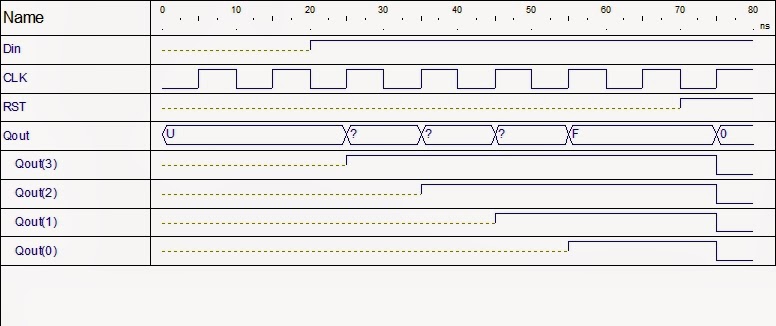
In the waveform graph above, the data input is 1 at 20 ns which is propagated through the D flip flops as shown by Qout(3), Qout(2), Qout(1) and Qout(0). At 70 ns Reset signal RST is applied which puts all the D flip flop states to 0.
Read More..

A book on Digital Synthesizers and Transmitters for Software Radio free download

This summary is not available. Please click here to view the post.
Read More..

Different method of adding component instances to an entity in VHDL

In the FPGA tutorial on how to add component instance in existing entity one method of adding was explained which is without library reference. In this post, other two method of adding instances to an entity are illustrated. The two methods are via VHDL library reference and using configuration declaration block.

The entity was a odd parity generator whose schematic is shown below.
parity generator schematic
The various ways of adding the xor gate was briefly talked in that post.

2. Without component declaration

In this method, library feature is used to add the xor gate. By this what it means is that, the xor gate component are referred using library reference. And in this case there is no need to define the component within the architecture body.

the main code line that references the library is,

instance_unit_name : entity work.component_name(current_entity_architecture_name)

The instance_unit_name is the name of the instance which is newly created. The entity term is required, the work is the library(directory) where the component(eg xor_gate) resides and the current_entity_architecture_name is name of the current entity architecture name.

Lets see the code of that used component declaration is,

library IEEE;
use IEEE.STD_LOGIC_1164.ALL;

entity parity is
    Port ( x1 : in  STD_LOGIC;
           x2 : in  STD_LOGIC;
           x3 : in  STD_LOGIC;
           x4 : in  STD_LOGIC;
           y : out  STD_LOGIC);
end parity;

architecture parity_arch of parity is

component xor_gate
Port ( a1 : in  STD_LOGIC;
             a2 : in  STD_LOGIC;
             b : out  STD_LOGIC);
end component;

signal int1, int2: std_logic;

begin

xor_unit1 : xor_gate
port map(a1 => x1, a2 => x2, b => int1);
xor_unit2 : xor_gate
port map(a1 => x3, a2 => x4, b => int2);

y <= int1 xor int2;

end parity_arch;


The code in red is the component declaration. When using library reference to add component instances, the component declaration in red is not required. At the same time, the component instantiation lines in yellow needs to be changed such that it references to library where the component gate vhdl code resides.

Making the necessary changes, the code for the parity generator becomes-

library IEEE;
use IEEE.STD_LOGIC_1164.ALL;

entity parity is
    Port ( x1 : in  STD_LOGIC;
           x2 : in  STD_LOGIC;
           x3 : in  STD_LOGIC;
           x4 : in  STD_LOGIC;
           y : out  STD_LOGIC);
end parity;

architecture parity_arch of parity is

signal int1, int2: std_logic;

begin

xor_unit1 : entity work.xor_gate(parity_arch)
port map(a1 => x1, a2 => x2, b => int1);
xor_unit2 : entity work.xor_gate(parity_arch)
port map(a1 => x3, a2 => x4, b => int2);

y <= int1 xor int2;

end parity_arch;


3. Using Configuration declaration:

Another method of adding component instance in the entity in VHDL is using configuration declaration. This differs from the above two methods in that, the port mapping is done in the architecture section while the VHDL library reference is done in a separate configuration section. Also the component declaration is added back.

The following code illustrates this.

library IEEE;
use IEEE.STD_LOGIC_1164.ALL;

entity parity is
    Port ( x1 : in  STD_LOGIC;
           x2 : in  STD_LOGIC;
           x3 : in  STD_LOGIC;
           x4 : in  STD_LOGIC;
           y : out  STD_LOGIC);
end parity;

architecture parity_arch of parity is

component xor_gate
Port ( a1 : in  STD_LOGIC;
             a2 : in  STD_LOGIC;
             b : out  STD_LOGIC);
end component;

signal int1, int2: std_logic;

begin

xor_unit1: xor_gate port map(x1, x2, int1);
xor_unit2: xor_gate port map(x3, x4, int2);

y <= int1 xor int2;

end parity_arch;

configuration parity_config of parity is

for parity_arch 
for xor_unit1 : xor_gate
use entity work.xor_gate(xor_arch);
end for;
for xor_unit2 : xor_gate
use entity work.xor_gate(xor_arch);
end for;
end for;

end parity_config;


Thus there are different method of adding the component instance to a entity.

See other FPGA tutorials also.
Read More..

Just Some Thoughts

Sorry I am on my soapbox again. It can be true or be evident that we do good things at our greatest and best work when we are inspire to do what we are passionate about. If you are passionate about something, then it will show and others will notice. And if not in most cases, in some cases, we may not do well under pressure or certain circumstances. Other times what we do comes natural. There is something special for each of us. This reminds me of that famous poem by Robert Frost that tells us that we should take the path not taken instead of the one that has been walked on before us. Then we should not go where the path led us but instead leave a trail.

The reason why the world lacks unity, and lies broken and in heaps, is, because man is disunited with himself. – Ralph Waldo Emerson

I think in 2010, a wonderful resolution is evolve into the person we intend to be. I think that will be a good one for me to accomplish in my social, academic and personal life. It’s not often I jump on my soapbox, but I felt like that this is something I need to tell someone… for my sake and to let others that they are not alone. I always feel like I want to give up and throw the town in, but I always keep my head up and remember why I’m going through certain situations. But at times I just dislike when people are not real. I mean they seem like they aren’t themselves…maybe they have to put on another persona in front of all the fame and fortunate, but up close and personal they may just be a different person. Hhmmm… knows because I don’t surely do not. Often times I want to go the place where I belong. I like that song Home by Daughtry. The band has pretty good songs. But I’ve heard the popular ones and not the ones that are not played from the rest of their albums. And I also think it would be sweet for me to find that special person next year. Yep. I have been riding the single train. And on the train are other people single, too, but I have not met the match yet, but I am sure that will change sometime soon. I don’t have nothing else to do so I decided to write and yes, I know, its long over due, but heck I had to give in from not writing. I was not purposely trying not to write, but there are days where I have those days. You know? I’m sure you have those days as well.

Read More..

World of Goo Full Español

World of Goo, Juego de puzzles en dos dimensiones cuya mecanica gira al rededor del uso de unas pequeñas creaturas en forma de bola llamadas Goo y compuesta por individuos de distintos colores y propiedades. El objetivo sera llevar el mayor numero posible de Goo hasta una tuberia generalmente colocada al otro extremo del escenario y superando diversos obstaculos en nuestro camino.
Seguir Leyendo...


Graficamente el titulo hace uso de un excelente y muy colorido motor en dos dimensiones con escenarios surrealistas de gran diseño y un sistema de fisicas estupendo que se adapta a las distintas propiedades de los Goo.

La curva de dificultad esta muy lograda y a medida que vallamos superando niveles encontraremos nuevos y divertidos retos que explotan las caracteristicas del escenario o las propiedades los Goo, ya sea su elasticidad, las capacidad de formar redes o su pegajosidad. Ademas en cada ecenario encontraremos carteles de mucho humor con pistas de como resolver el puzzle y una muy divertida historia.

Requisitos:
*Sistema operativo: Windows ® XP o Vista
*Procesador: 1 GHz o más rápido
*Memoria: 256 MB de RAM
*Tarjeta de Video: Cualquier Tarjeta gráfica 3D de menos de 5 años
*Tarjeta de sonido: compatible DirectX 9.0c
*DirectX: ® Versión: 9.0c
*Espacio en disco: 100 MB
*UNIDAD: CD-ROM
*Perifericos: Teclado y Raton

Descarga:
RapidShare

Parte 1 Parte 2


Read More..

McAfee AVERT Stinger 10 2 0 936 Free Download

McAfee AVERT Stinger 10.2.0.936 Free Download
Free PROGRAMS

Stinger is a stand-alone utility used to detect and remove specific viruses.

McAfee AVERT Stinger is not a substitute for the full anti-virus protection, but rather a tool that assists administrators and users when dealing with an infected system.

Stinger utilizes next generation scan engine technology, including process scanning, digitally signed DAT files, and scan performance optimizations.

This version of Stinger includes detection for all known variants :

· BackDoor-ALI
· BackDoor-AQJ
· BackDoor-AQJ.b
· BackDoor-CEB
· BackDoor-CEB!bat
· BackDoor-CEB!hosts
· BackDoor-CEB.b
· BackDoor-CEB.c
· BackDoor-CEB.d
· BackDoor-CEB.dll
· BackDoor-CEB.dr
· BackDoor-CEB.e
· BackDoor-CEB.f
· BackDoor-CEB.sys
· BackDoor-CFB
· BackDoor-JZ
· BackDoor-JZ.dam
· BackDoor-JZ.dr
· BackDoor-JZ.gen
· BackDoor-JZ.gen.b
· Bat/Mumu.worm
· Downloader-DN.a
· Downloader-DN.b
· Exploit-DcomRpc
· Exploit-DcomRpc.b
· Exploit-DcomRpc.dll
· Exploit-Lsass
· Exploit-Lsass.dll
· Exploit-MS04-011
· Exploit-MS04-011.gen
· HideWindow
· HideWindow.dll
· IPCScan
· IRC/Flood.ap
· IRC/Flood.ap.bat
· IRC/Flood.ap.dr
· IRC/Flood.bi
· IRC/Flood.bi.dr
· IRC/Flood.cd
· NTServiceLoader
· ProcKill
· PWS-Narod
· PWS-Narod.dll
· PWS-Narod.gen
· PWS-Sincom
· PWS-Sincom.dll
· PWS-Sincom.dr
· W32/Anig.worm
· W32/Anig.worm.dll
· W32/Bagle
· W32/Bagle!eml.gen
· W32/Bagle!pwdzip
· W32/Bagle.ad!src
· W32/Bagle.dldr
· W32/Bagle.dll.dr
· W32/Bagle.eml
· W32/Bagle.fb!pwdzip
· W32/Bagle.fc!pwdzip
· W32/Bagle.fd!pwdzip
· W32/Bagle.fe!pwdzip
· W32/Bagle.fm.dldr
· W32/Bagle.gen
· W32/Bagle@MM!cpl
· W32/Blaster.worm
· W32/Blaster.worm.k
· W32/Bropia.worm
· W32/Bugbear
· W32/Bugbear.a.dam
· W32/Bugbear.b!data
· W32/Bugbear.b.dam
· W32/Bugbear.gen@MM
· W32/Bugbear.h@MM
· W32/Bugbear@MM
· W32/Deborm.worm.ah
· W32/Deborm.worm.gen
· W32/Doomjuice.worm
· W32/Dumaru
· W32/Dumaru.ad@MM
· W32/Dumaru.al.dll
· W32/Dumaru.dll
· W32/Dumaru.eml
· W32/Dumaru.gen
· W32/Dumaru.gen@MM
· W32/Dumaru.w.gen
· W32/Elkern.cav
· W32/Elkern.cav.c
· W32/Elkern.cav.c.dam
· W32/Fizzer
· W32/Fizzer.dll
· W32/FunLove
· W32/FunLove.apd
· W32/Gaobot.worm
· W32/Harwig.worm
· W32/IRCbot
· W32/IRCbot.worm
· W32/IRCbot.worm.dll
· W32/Klez
· W32/Klez.dam
· W32/Klez.eml
· W32/Klez.gen.b@MM
· W32/Klez.rar
· W32/Korgo.worm
· W32/Lirva
· W32/Lirva.c.htm
· W32/Lirva.eml
· W32/Lirva.gen@MM
· W32/Lirva.htm
· W32/Lirva.txt
· W32/Lovgate
· W32/Mimail
· W32/Mimail.c@MM
· W32/Mimail.c@MM
· W32/Mimail.i!data
· W32/Mimail.q@MM
· W32/MoFei.worm
· W32/MoFei.worm.dr
· W32/Mumu.b.worm
· W32/Mydoom
· W32/Mydoom!bat
· W32/Mydoom!ftp
· W32/Mydoom.b!hosts
· W32/Mydoom.dam
· W32/Mydoom.t.dll
· W32/Mytob
· W32/Mytob.gen@MM
· W32/Mytob.worm
· W32/MyWife
· W32/MyWife.dll
· W32/MyWife@MM
· W32/Nachi!tftpd
· W32/Nachi.worm
· W32/Netsky
· W32/Netsky.af@MM
· W32/Nimda
· W32/Nimda.dam
· W32/Nimda.eml
· W32/Nimda.gen@MM
· W32/Nimda.htm
· W32/Pate
· W32/Pate!dam
· W32/Pate.dam
· W32/Pate.dr
· W32/Polip
· W32/Polip!mem
· W32/Polybot
· W32/Polybot.bat
· W32/Sasser.worm
· W32/Sasser.worm!ftp
· W32/Sdbot
· W32/Sdbot!irc
· W32/Sdbot.bat
· W32/Sdbot.cli
· W32/Sdbot.dll
· W32/Sdbot.dr
· W32/Sdbot.worm
· W32/Sdbot.worm!ftp
· W32/Sdbot.worm.bat.b
· W32/Sdbot.worm.dr
· W32/Sdbot.worm.gen
· W32/Sdbot.worm.gen.a
· W32/Sdbot.worm.gen.b
· W32/Sdbot.worm.gen.c
· W32/Sdbot.worm.gen.d
· W32/Sdbot.worm.gen.e
· W32/Sdbot.worm.gen.q
· W32/Sober
· W32/Sober!data
· W32/Sober.dam
· W32/Sober.eml
· W32/Sober.f.dam
· W32/Sober.g.dam
· W32/Sober.q!spam
· W32/Sober.r.dr
· W32/Sober.r@MM
· W32/Sobig
· W32/Sobig.dam
· W32/Sobig.eml
· W32/Sobig.f.dam
· W32/Sobig.gen@MM
· W32/Spybot.worm
· W32/SQLSlammer.worm
· W32/Swen
· W32/Swen@MM
· W32/Yaha.eml
· W32/Yaha.gen@MM
· W32/Yaha.y@MM
· W32/Yaha@MM
· W32/Zafi
· W32/Zafi.b.dam
· W32/Zindos.worm
· W32/Zotob.worm
· W32/Zotob.worm!hosts

Note: Windows ME and XP utilize a restore utility that backs up selected files automatically to the C:_Restore folder.

This means that an infected file could be stored there as a backup file, and VirusScan will be unable to delete these files. You must disable the System Restore Utility to remove the infected files from the C:_Restore folder.
Whats New in This Release:
New Detections:
· FakeAlert-SecurityTool.gy
· PWS-Zbot.gen.ats
· PWS-Zbot.gen.att
· PWS-Zbot.gen.atu
· ZeroAccess.ib

Enhanced Detections:

· Exploit-CVE2010-0188
· FakeAlert-SecurityTool
· FakeAlert-SecurityTool.gw
· Generic Downloader.os
· Generic Downloader.z
· JS/Exploit-Blacole.gc
· JS/Exploit-Blacole.ht
· Medfos.e
· PWS-Zbot.gen.ach
· PWS-Zbot.gen.ajn
· PWS-Zbot.gen.anm
· PWS-Zbot.gen.any
· PWS-Zbot.gen.aru
· PWS-Zbot.gen.arw
· PWS-Zbot.gen.ary
· PWS-Zbot.gen.asp
· PWS-Zbot.gen.asz
· PWS-Zbot.gen.atl
· PWS-Zbot.gen.atn
· PWS-Zbot.gen.ato
· PWS-Zbot.gen.atr
· W32/Autorun.worm.eu
· ZeroAccess.hr

Click Here to Download
program4secure.blogspot.com
Read More..

Interfacing Intel 8086 with Intel 8251 USART and MAX232

In order to communication over serial lines such as telephone lines we need to connect the microprocessor to a USART. The microprocessor sends parallel 8 bit data to the USART. The USART latches the data byte into its register and inserts start bit, parity bit and one or more stop bits. This character frame is then serialized using Parallel to serial converter and send out in serially by the performing shifting operation. The signal coming out of the USART is TTL signals which has not enough strength to be send over long distance. So this TTL signal is converted to the higher voltage by voltage converter. MAX232 is a device that converts TTL voltages levels(0 to 0.8V for logic 0 and 2V to Vcc for logic 1) to RS232 voltage levels(-3 to -15V for logic 0 and +3 to +15V for logic 1) and from RS232 voltage levels to TTL voltage levels. The output from the MAX232 are thus RS232 signals and connected to a male DB25 connector or 9 DB connector. The DB25 or DB9 connector are connected to the female DB25 or female 9DB connected. The DB25 female/DB9 female connector are connected to the MODEM which is a DCE(Data Communication Equipment).

The following schematic shows how a 8086 microprocessor is interfaced with intel 8251 USART which is in turn connected to the MAX232 transceiver and finally to the DB25 connector.


The overview of the connection was explained previously. Now a more detailed explanation will follow. Looking at the 8251 chip the important pins or signals are the DTR, DSR, RTS and CTS. These are all control signals. The DTR and DSR signals are used to initialize the DTE(microprocessor or CPU or Computer) and the modem. The RTS and CTS are control signals which are inserted before data transfer. The MAX232 has two drivers and two receivers. In the figure above the TxD and RxD are the pins over which the serial data is sent. These are connected to the T1IN and R1OUT respectively. Similarly the RTS and CTS signals are connected to the T2OUT and R2IN.
Read More..

Menambah Utility untuk Aplikasi Penjualan Buku


Buka Aplikasi Penjualan Buku yang sudah dibuat > Project tambahkan sebuah Form Baru > Lalu desain tampilannya seperti pada gambar berikut :


Buka database JualBuku.accdb, tambahkan tabel baru dengan nama Pemakai dan struktur tabelnya sebagai berikut :
Field
Type
Size
Keterangan
Kode_Pmk
Text
10
Primary Key
Nama_Pmk
Text
50

Status_Pmk
Text
15

Password_Pmk
Text
10


Jangan lupa untuk menyimpan kembali hasil yang sudah dibuat.

Download Modul Lengkapnya disini


Read More..

Download Matlab


Mathworks Matlab 7.1.4 R14 SP3 Retail Edition
1.46 GB | ISO | 16 RAR Parts
MATLAB® - The Language of Technical Computing

MATLAB is a high-level language and interactive environment that enables
you to perform computationally intensive tasks faster than with traditional programming languages such as C, C++, and Fortran.

* Introduction and Key Features
* Developing Algorithms and Applications
* Analyzing and Accessing Data


* Visualizing Data
* Performing Numeric Computation
* Publishing Results and Deploying Applications

* MATLAB Add–On Products
* MATLAB Applications

MATLAB is the foundation for Simulink and all other MathWorks products, and can be extended with add-on products for:
Hide Section Math and Optimization

* Optimization Toolbox
* Symbolic Math Toolbox
* Extended Symbolic Math Toolbox
* Partial Differential Equation Toolbox
* Genetic Algorithm and Direct Search Toolbox

Hide Section Statistics and Data Analysis

* Statistics Toolbox
* Neural Network Toolbox
* Curve Fitting Toolbox
* Spline Toolbox
* Model-Based Calibration Toolbox

Hide Section Control System Design and Analysis

* Control System Toolbox
* System Identification Toolbox
* Fuzzy Logic Toolbox
* Robust Control Toolbox
* Model Predictive Control Toolbox
* Aerospace Toolbox

Hide Section Signal Processing and Communications

* Signal Processing Toolbox
* Communications Toolbox
* Filter Design Toolbox
* Filter Design HDL Coder
* Wavelet Toolbox
* Fixed-Point Toolbox
* RF Toolbox
* Link for Code Composer Studio™
* Link for ModelSim®
* Link for Cadence Incisive

Hide Section Image Processing

* Image Processing Toolbox
* Image Acquisition Toolbox
* Mapping Toolbox

Hide Section Test & Measurement

* Data Acquisition Toolbox
* Instrument Control Toolbox
* Image Acquisition Toolbox
* SystemTest
* OPC Toolbox

Hide Section Financial Modeling and Analysis

* Financial Toolbox
* Financial Derivatives Toolbox
* GARCH Toolbox
* Datafeed Toolbox
* Fixed-Income Toolbox

Hide Section Application Deployment

* MATLAB® Compiler
* Excel Link
* MATLAB® Builder for Excel®
* MATLAB® Builder for .NET
* MATLAB® Builder for Java™

Hide Section Database Connectivity and Reporting

* Database Toolbox
* MATLAB® Report Generator

Hide Section Distributed Computing

* Distributed Computing Toolbox
* MATLAB Distributed Computing Engine


DOWNLOAD:

http://depositfiles.com/files/6060407
http://depositfiles.com/files/6060436
http://depositfiles.com/files/6060469
http://depositfiles.com/files/6060516
http://depositfiles.com/files/6060540
http://depositfiles.com/files/6060591
http://depositfiles.com/files/6060898
http://depositfiles.com/files/6061684
http://depositfiles.com/files/6064588
http://depositfiles.com/files/6064750
http://depositfiles.com/files/6064780
http://depositfiles.com/files/6064804
http://depositfiles.com/files/6065038
http://depositfiles.com/files/6065185
http://depositfiles.com/files/6065200
http://depositfiles.com/files/6065419
Read More..

how to create and use functions in VHDL

This is a continuation of the tutorial- how to create and use functions in VHDL. In this tutorial we show how a function can be declared inside an entity section. In the last two tutorials we showed how a function can be declared in a package and how a function can be declared inside the architecture.

The code below is the function we created that accepts two inputs of the type std_logic_vector and outputs one parameter also of the type std_logic_vector.

FUNCTION myAdder(signal f1,f2: STD_LOGIC_vector(3 downto 0)) return std_logic_vector IS
    variable sum_int : integer := 0;
    variable sum : std_logic_vector(3 downto 0) := "0000";
BEGIN
 
    sum_int := to_integer(unsigned(f1)) + to_integer(unsigned(f2));
 
    sum := std_logic_vector(to_unsigned(sum_int,4));
 
    return sum;
 
END FUNCTION myAdder;

As you might already guessed from the two earlier tutorials, once you have create the function VHDL code, the placement of the function is just matter of copying and pasting the code inside a package or architecture declarative part. The placement of function code in entity is similar of that of architecture method. The function code is just placed after the port declaration and the function is called in the architecture after the begin keyword.

 The following shows where to place the function code in the function declaration in entity method:

 library ieee;
use ieee.std_logic_1164.all;
use ieee.numeric_std.all;

entity function_test is
    port(
    a : in std_logic_vector(3 downto 0);
    b : in std_logic_vector(3 downto 0);
    y : out std_logic_vector(3 downto 0)
    );
 
FUNCTION myAdder(signal f1,f2: STD_LOGIC_vector(3 downto 0)) return std_logic_vector IS
    variable sum_int : integer := 0;
    variable sum : std_logic_vector(3 downto 0) := "0000";
BEGIN
 
    sum_int := to_integer(unsigned(f1)) + to_integer(unsigned(f2));
 
    sum := std_logic_vector(to_unsigned(sum_int,4));
 
    return sum;
 
END FUNCTION myAdder;

end function_test;

architecture model of function_test is

begin
 
    y <= myAdder(a, b);

end model;

 There is difference in the package method though. In the package method, we declared the function header inside the package header and the whole function(header and body) inside the package body.

In case of entity and architecture method, the whole function code(header and body) is declared inside the entity or architecture whichever method is used. 

Read More..

How to design Ripple Carry Adder using For Loop in VHDL

This VHDL tutorial shows how to design Ripple Carry Adder using For Loop in VHDL. A ripple carry adder is one in which the carry output from each full adder circuit is propagated to the next full adder to contribute to the calculation. A Loop statement is one of the four sequential statement in VHDL. The others are the IF statement, Case statement and the Wait statement.

The Loop statement is used with other VHDL keywords such as For, While, Next and Exit. So there are different forms of Loop statement depending upon which(For, While, Next and Exit) keyword is used. Here we illustrate the Loop statement with For keyword for the design of Ripple Carry Adder.

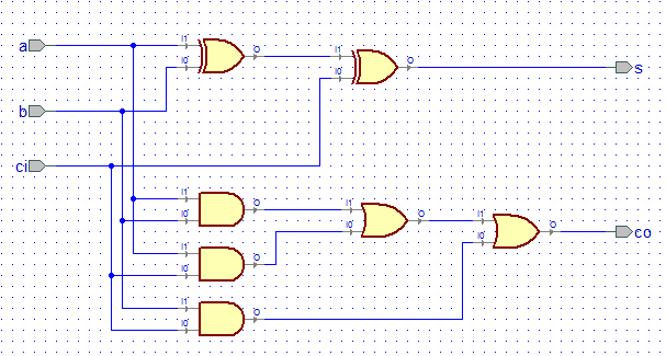
One Full adder has 3 inputs, the two input bits for the number to be added, one carry input from previous calculation and two outputs- the sum and carry out. Schematic symbol of a Full Adder is shown below:


Internally the Full Adder is constructed using basic logic gates implementing the Boolean function of a full adder circuit as follows-

full adder circuit

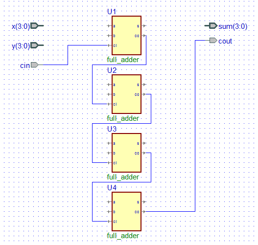
Now the carry ripple term refers to the fact that the previous carry input is the input to the carry input of the first adder. The first adder carry output is connected to the next full adder carry input, whose carry output is again connected to the next full adder carry input and so on as illustrated by the diagram below:

carry propagation in ripple carry adder

When one looks at the Boolean equation for the N bit adder implementation for each of the full adder we see that there is some repetivitive structure in the code:

first adder:
        sum(0) = x(0) xor y(0) xor c(0);
        c(1) := (x(0) and y(0)) or (x(0) and c(0)) or (y(0) and c(0));
 where c(1) is from the first adder

second adder:
        sum(1) = x(1) xor y(1) xor c(1);
        c(2) := (x(1) and y(1)) or (x(1) and c(1)) or (y(1) and c(1));

 third adder:
        sum(2) = x(2) xor y(2) xor c(2);
        c(3) := (x(2) and y(2)) or (x(2) and c(2)) or (y(2) and c(2)); 

fourth adder:
        sum(3) = x(3) xor y(3) xor c(3);
        c(4) := (x(3) and y(3)) or (x(3) and c(3)) or (y(3) and c(3));

So if we take c(0) to be cin of the carry input of the 4 bit adder and c(4) the cout of the 4 bit adder then the 4 bit adder can be designed.

Because of the repetivitive structure in the code we can use for loop to implement the structure,

for k in 0 to 3 loop
      sum(k) = x(k) xor y(k) xor c(k);
        c(k+1) := (x(k) and y(k)) or (x(k) and c(k)) or (y(k) and c(k));
end loop;

To use the above VHDL loop code we need the c to be of variable type and having a bit vector length of 5 bits- 4 downto 0 if signal x and y and sum are 3 downto 0.

The complete ripple carry adder VHDL code is below:


library ieee;
use ieee.std_logic_1164.all;

entity ripple_carry_adder is
    port(
    x : in std_logic_vector(3 downto 0);
    y : in std_logic_vector(3 downto 0);
    cin : in std_logic;
    sum : out std_logic_vector(3 downto 0);
    cout : out std_logic
    );
end ripple_carry_adder;

architecture model of ripple_carry_adder is

begin
    process(x,y,cin)
        variable c : std_logic_vector(4 downto 0);
    begin       
        c(0) := cin;
    for k in 0 to 3 loop
        sum(k) <= x(k) xor y(k) xor c(k);
        c(k+1) := (x(k) and y(k)) or (x(k) and c(k)) or (y(k) and c(k));
    end loop;
   
    cout <= c(4);
   
    end process;
       
end model;

The schematic model is shown below:
 
 The following shows the simulated waveform for this adder using VHDL software:

ripple carrry adder simulation vhdl software

So, this vhdl tutorial showed you how and why a for loop vhdl statement can be used for modelling ripple carry adder.
Read More..

How to realize encoder function in VHDL

There are many ways in which encoder function can be implemented in VHDL. Here 4 different techniques with VHDL codes are provided.

Suppose we to design an encoder which outputs y with sel input as follows,

when sel is 00, y is 1110
when sel is 01, y is 1101
when sel is 10, y is 1011
when sel is 11, y is 0111

So the input sel is 2 bit and output y is 4 bit. The the encoder entity can be declared as follows-

entity encoder is
    port(
    sel : in std_logic_vector(1 downto 0);
    y : out std_logic_vector(3 downto 0)
    );
end encoder;

Now there are different ways to realize the encoder function.

1. Using if then elsif statements inside a process

architecture arch1 of encoder is
begin
    process(sel)
    begin
        y <= (yrange => 1);
        if (sel = "00") then y(0) <= 0;
        elsif (sel = "01") then y(1) <= 0;
        elsif (sel = "10") then y(2) <= 0;
        else y(3) <= 0;
        end if;
    end process;
end arch1;

2. Using case statement inside a process

architecture arch2 of encoder is
begin
    process(sel)
    begin
        y <= (yrange => 1);
        case sel is
            when "00" => y(0) <= 0;
            when "01" => y(1) <= 0;
            when "10" => y(2) <= 0;
            when others => y(3) <= 0;
        end case;
    end process;
   
end arch2;

3. Using simple select statement

architecture arch3 of encoder is
begin
    with sel select
    y <= "1110" when "00",
    "1101" when "01",
    "1011" when "10",
    "0111" when others;
end arch3;

4. Using conversion of sel inputs bits to integer and setting it to 0

architecture arch4 of encoder is
begin
    process(sel)
    begin
        y <= (yrange => 1);
        y(to_integer(unsigned(sel))) <= 0;
    end process;
end arch4;
Read More..
Powered by Blogger.